Many problems in continuum mechanics can be reduced to two dimensions, when the geometry and the loading of a body allow one of the three directions to be treated separately. The two most common idealizations are plane stress, for bodies that are very thin in one direction, and plane strain, for bodies that are very long in one direction. In both cases the analysis is carried out in the plane x1x2, but the out-of-plane behaviour is different, as shown below.
In the following, εij is the (small) strain tensor and, for an isotropic linear elastic material with Young’s modulus E and Poisson’s ratio ν, the stresses and strains are related by Hooke’s law:
εij=E1+νσij−Eνσkkδij(1)
Plane stress
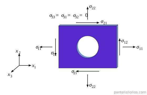
Plane stress is a special state of stress that occurs in bodies in which one dimension is very small compared to the other two. Consider a very thin plate, as shown in Fig. 1. The two faces normal to x3 are free of tractions, so the normal and shear stresses acting on them, σ33, σ31 and σ32, are zero there. Because the plate is very thin, we may assume that these components remain approximately zero throughout the whole body:
σ33=σ31=σ32=0(2)
For this assumption to hold, the external loads must act in the plane of the plate (they have no component in the direction of x3) and be distributed uniformly over its thickness.
Figure 1: Thin plate with a hole under plane stress conditions. The loads act in the plane of the plate; the stresses on the faces normal to x3 are zero.
The stress tensor then takes the form:
σij=σ11σ210σ12σ220000(3)
and it can be reduced to the two-dimensional tensor:
σαβ=[σ11σ21σ12σ22],α,β=1,2(4)
Since the stress tensor is symmetric, σ12=σ21, only three independent stress components remain: σ11, σ22 and σ12. Thin bodies under plane stress can therefore be analyzed as two-dimensional. Note that the plane stress assumption is valid only if the plate does not buckle or bend out of its plane.
The axis x3 is always a principal direction, with a principal stress equal to zero, so the third invariant of the stress tensor vanishes, I3=0 (see Principal stresses and stress invariants). The two in-plane principal stresses and their directions follow from the two-dimensional analysis presented in the article Mohr’s circle.
Although the out-of-plane stresses are zero, the out-of-plane normal strain is not: the plate becomes thinner or thicker as it is loaded. Setting σ33=σ31=σ32=0 in Hooke’s law, Eq. (1), gives:
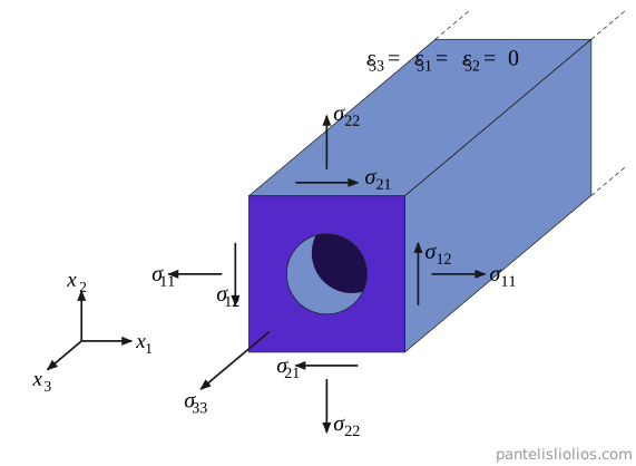
Plane strain is the opposite case: it occurs in bodies in which one dimension is very large compared to the other two, e.g. a long tunnel, a dam or a retaining wall (Fig. 2). For plane strain conditions:
the geometry of the cross section does not change along the long axis x3;
the loads act in the plane of the cross section (x1x2) and do not vary along x3;
the body cannot deform in the direction of x3, either because its ends are restrained or because the cross section of interest is far from the ends.
Figure 2: Long body with a tunnel under plane strain conditions. The loads act in the plane of the cross section and do not vary along x3; the strain along the long axis is zero.
Under these conditions every cross section deforms in the same way, and the displacement field takes the form:
u1=u1(x1,x2),u2=u2(x1,x2),u3=0(7)
From the definition of the small strain tensor, εij=21(ui,j+uj,i) (see Index notation for the comma notation), the out-of-plane strains vanish, since u3=0 and u1, u2 do not depend on x3:
ε33=ε31=ε32=0(8)
so the strain tensor takes the form:
εij=ε11ε210ε12ε220000(9)
In this case it is the out-of-plane normal stress that does not vanish. From Hooke’s law, Eq. (1), the condition ε33=0 gives:
while ε31=ε32=0 gives σ31=σ32=0. The stress tensor therefore takes the form:
σij=σ11σ210σ12σ22000ν(σ11+σ22)(11)
As in plane stress, the axis x3 is a principal direction, but now the corresponding principal stress is σ33, which is in general not zero, and so I3=0. Since σ33 depends only on σ11 and σ22, the problem is still two-dimensional: the unknowns are the three in-plane stresses σ11, σ22 and σ12. Substituting σ33 into Hooke’s law, the in-plane strains are:
Comparing Eqs. (6) and (12), the plane strain relations are obtained from the plane stress relations if E and ν are replaced by:
E′=1−ν2E,ν′=1−νν(13)
This is useful in practice: a solution derived for plane stress can be converted to plane strain (and vice versa) simply by changing the elastic constants.
In rock mechanics, plane strain is the more common assumption, since many structures in rock, such as tunnels and long excavations, are long compared to their cross section. In laboratory testing, on the other hand, thin specimens such as the discs of the Brazilian (indirect tensile) test are usually analyzed under plane stress conditions.
Comparison
Table 1: Comparison of plane stress and plane strain (isotropic linear elastic material).